Move beyond guesswork. Understand the invisible forces that keep your house standing—and how to work with them safely during renovations.
Your home’s structure operates silently beneath drywall, flooring, and finishes—a carefully balanced system of forces, materials, and geometry working continuously to keep you safe. When renovation dreams arise—a wider doorway, an open-concept kitchen, a new deck—this hidden framework becomes critically visible. Misunderstanding loads, spans, or strength isn’t merely academic; it risks progressive damage, compromised safety, or costly repairs. This guide translates structural engineering fundamentals into clear, actionable knowledge grounded in building science and widely adopted residential standards. You’ll learn to recognize critical elements, avoid common misconceptions, trace load paths confidently, and know precisely when professional expertise isn’t optional—it’s essential. No unverified claims. No oversimplifications that endanger safety. Just principle-based understanding to steward your home wisely.
Introduction: Why Structure Isn’t Just “Walls and Beams”
Walk into any room of your home. The ceiling feels solid. The floor supports your weight without complaint. Walls stand straight for decades. This reliability emerges from deliberate design choices governed by physics and codified in widely referenced standards like the International Residential Code (IRC). These documents synthesize decades of research, material science, and lessons from structural performance across diverse climates and soil conditions. They establish minimum safety thresholds—not aspirational ideals. Understanding the language of structure—loads, spans, strength—isn’t about turning you into an engineer. It’s about cultivating contextual awareness. It’s the difference between confidently discussing options with a contractor and signing documentation you don’t fully grasp. It’s recognizing that the wall you want to modify might be quietly supporting critical weight above. This foundational knowledge honors the craft of building while safeguarding your greatest investment. As we explore these concepts, remember: structural integrity is non-negotiable. Curiosity paired with caution defines responsible homeownership.
The Three Pillars Framework: Loads, Spans, Strength
Imagine your home’s structure as a relay race. Loads are the baton—the weight and forces that must be carried. Spans define the distance each runner (structural member) must cover while holding that baton. Strength is the runner’s capacity—the ability to carry the load across the span without compromising safety or function. Break any link, and the entire system falters. This framework isn’t theoretical; it’s the mental model used by design professionals and experienced builders to diagnose concerns and develop solutions. Mastering these three interconnected pillars transforms how you see your home.
Pillar 1: Loads – The “What” That Must Be Carried
A load is any force acting upon a structure. Not all loads behave alike. Confusing them leads to critical oversights. Let’s examine the primary load categories in residential contexts, with practical illustrations.
Dead Loads: The Permanent Weight
Dead loads are constant, unchanging weights of the structure itself and permanently attached elements—your building’s foundational mass.
– Examples: Roof framing with sheathing and roofing materials; floor systems (joists, subfloor, finished flooring); walls (studs, sheathing, drywall, insulation); built-in cabinetry; masonry features; foundation elements.
– Why it matters: Dead loads accumulate predictably but significantly. Adding a tile floor over existing subfloor increases dead load on joists. Installing stone veneer on an upper-level wall concentrates weight on framing below. During renovations, always account for added dead load. Typical asphalt shingle roofs weigh approximately 2–3.5 pounds per square foot (psf); clay or concrete tile can range from 9 to 12+ psf depending on product and installation—a substantial increase your existing framing may not accommodate.
– Common oversight: Assuming “it’s always been there, so it’s fine.” Original construction met minimum standards for its era. Adding even modest dead load (like converting an attic access space into storage) can gradually exceed safe limits. Visible sagging or persistent floor bounce often signals overloaded conditions.
Live Loads: The Temporary, Variable Forces
Live loads are transient forces—people, furniture, snow, wind. They’re dynamic, location-specific, and probabilistic.
– Examples:
– Occupancy: People gathered in a living area (IRC references 40 psf minimum for general living spaces; 30 psf for bedrooms).
– Snow: Light dusting adds minimal load; wet, heavy snow can exceed 30 psf. Roof pitch influences accumulation—low-slope roofs retain more.
– Wind: Generates uplift (lifting forces on roofs) and lateral pressure (pushing walls sideways). Exposure matters—homes on hillsides, near water, or in open terrain face higher demands.
– Seismic: Ground motion during earthquakes creates complex lateral and vertical forces (critical in designated seismic regions).
– Why it matters: Live loads dictate design for intended use. A home office with dense bookshelves in one corner creates localized loading far exceeding average values. A deck designed for light seating becomes hazardous when accommodating large gatherings or heavy equipment. Regional snow load requirements vary significantly—building departments specify ground snow values based on historical climate data. Ignoring location-specific expectations introduces risk.
– Nuance: Codes define probable maximum loads based on statistical analysis. Structures include safety margins, but chronic overloading (e.g., heavy attic storage year after year) contributes to material fatigue over time.
Environmental Loads: Nature’s Persistent Influence
Often grouped with live loads but distinct in origin and long-term impact:
– Soil Pressure: Lateral force against foundation walls. Poor drainage increases hydrostatic pressure, potentially causing bowing or cracking.
– Frost Action: In cold climates, water-saturated soil freezes and expands upward. Footings placed below the local frost depth mitigate this risk.
– Thermal Movement: Materials expand and contract with temperature shifts. Long structural runs without accommodation (like expansion joints in concrete) may develop stress cracks. Wood framing accommodates movement better but still requires thoughtful detailing.
– Moisture Intrusion: While not a “load” in the force sense, moisture weakens structural materials over time (rot in wood, corrosion in connectors), effectively reducing strength. This underscores why ventilation in crawl spaces and attics is structurally relevant.
Load Paths: The Non-Negotiable Journey
This is the most vital concept: Every load must travel uninterrupted from its origin down to stable ground. Visualize pouring water on your roof—it flows downward through defined channels. Loads follow a similar path—but through solid materials.
– Example Path (Roof Snow Load): Snow → Roof Sheathing → Rafters/Trusses → Top Plate of Supporting Wall → Wall Studs → Bottom Plate → Floor System (if applicable) → Foundation Wall → Footing → Stable Soil.
– Critical Insight: Interruptions create risk. Removing a section of wall without installing a properly sized header (beam) to carry the load above breaks the path. The load transfers unpredictably to adjacent members, potentially causing cracks, deflection, or progressive damage. Always trace the path: Where does this weight go next? What supports that support?
The Fundamental Principle: Structure is a continuous dialogue between gravity, geometry, and material capacity. Loads define the demand (“How much weight?”); spans define the challenge (“How far must it travel?”); strength provides the capacity (“Can this assembly handle it safely?”). Disrupt the dialogue, and the structure communicates distress through visible signs.
Pillar 2: Spans – The “How Far” Challenge
Span is the unsupported horizontal distance a structural member (joist, beam, rafter) bridges between supports (walls, beams, columns). Span isn’t merely a measurement—it’s the primary factor influencing how much a member deflects (bends) under load. Physics is precise here: deflection increases with the cube of the span. Double the span? Deflection increases eightfold. This exponential relationship is why verified span references exist and why estimation is unsafe.
Why Span Dictates Performance
- Deflection vs. Failure: A member may resist breaking (ultimate strength) yet deflect excessively under normal use (serviceability limit). Excessive deflection cracks finishes, jams doors, creates drainage issues on low-slope roofs, or feels unsettling underfoot. Codes limit allowable deflection (e.g., L/360 for live loads on floors—meaning a 12-foot span may deflect no more than 0.4 inches).
- Span Depends on Multiple Factors:
- Material Properties: Southern Pine typically supports longer spans than Spruce-Pine-Fir (SPF) at identical dimensions. Higher grades (fewer knots/defects) outperform lower grades.
- Member Dimensions: Depth influences stiffness more than width—increasing depth significantly reduces deflection.
- Load Magnitude: Heavier loads (snow, dense flooring) require shorter spans.
- Spacing: Joists at 16-inch centers carry less load per member than those at 24-inch centers, permitting slightly longer spans.
- Illustrative Span Reference (Floor Joists, 40 psf Live Load):
| Lumber Type | 2×8 @ 16″ o.c. | 2×10 @ 16″ o.c. | 2×12 @ 16″ o.c. |
|————-|—————-|—————–|—————–|
| SPF (#2) | ~11′ 0″ | ~14′ 0″ | ~16′ 6″ |
| Southern Pine (#2) | ~12′ 6″ | ~16′ 0″ | ~19′ 0″ |
Note: These values are simplified examples for illustration only. Actual allowable spans depend on numerous site-specific factors including lumber grade stamp verification, moisture content, local building code requirements (snow, wind), intended use, and deflection criteria. Always consult the most current span tables published by the American Wood Council, engineered drawings, or a qualified professional for your specific project.
Common Span Misconceptions in Renovations
- The “It’s Held Up This Long” Assumption: An existing 2×8 spans 13 feet in an older home. Absence of collapse doesn’t confirm adequacy. Original materials may have differed; added loads (new flooring, storage); environmental exposure (moisture, insects); or changed usage may have reduced capacity. What was marginally acceptable decades ago may no longer be safe.
- The “Sistering Will Fix It” Oversimplification: Adding a new joist alongside an existing one (sistering) can increase capacity—but only with full-length bonding using structural adhesive and closely spaced fasteners per engineering guidance. Incomplete sistering creates false confidence with minimal actual benefit.
- Cantilevers: The Overhang Consideration: Decks, bay windows, and roof eaves often extend beyond primary support. Codes typically limit cantilever length to ≤ 1/4 of the backspan within the structure. A joist with a 12-foot interior span generally cantilevers no more than 3 feet. Exceeding limits risks excessive deflection or instability.
Measuring Span Accurately
- Span is measured between points of support, not wall surface to wall surface. For beams on columns, measure from centerline to centerline.
- For sloped roofs, span tables use the horizontal projection, not the sloped rafter length. A rafter on a 6/12 pitch spanning 20 feet horizontally has a sloped length of ~22.4 feet—but design references use the 20-foot horizontal value.
- Practical Check: When assessing existing conditions, look for signs of excessive span: persistent floor bounce under normal walking, visible sag (verified with a taut string line), or diagonal drywall cracks radiating from window/door corners on walls below long spans.
Pillar 3: Strength – The “Can It Handle It?” Capacity
Strength describes a member’s ability to resist loads without failure (breaking, crushing, buckling) or excessive deformation. It’s not a single value—it’s a collection of interrelated properties shaped by material, geometry, connections, and environment.
Key Strength Properties Clarified
- Bending Strength (Flexural): Resistance to breaking when bent (e.g., a floor joist under load). Governs sizing for most horizontal members. Relevance: Headers over wide openings require sufficient bending strength to prevent sagging that damages finishes above.
- Shear Strength: Resistance to internal sliding or tearing forces parallel to the grain. Highest near supports. Relevance: Deep notching near a joist end (where shear stress peaks) can cause sudden failure even if bending capacity seems adequate. Codes strictly limit notching location and depth.
- Compression Strength (Parallel to Grain): Resistance to crushing along the wood fibers (e.g., a column). Wood performs well here. Relevance: Short posts rarely fail in pure compression, but long, slender columns may buckle—a stability issue requiring bracing.
- Tension Strength: Resistance to being pulled apart. Wood is strong in tension parallel to grain. Relevance: Bottom chords of roof trusses operate in tension; metal connector plates must transfer this force reliably.
- Bearing Strength (Perpendicular to Grain): Resistance to crushing across the wood fibers (where a joist rests on a wall plate). Wood is significantly weaker here. Relevance: A beam resting on a narrow wall without adequate bearing area can crush the supporting wood, causing settlement. Codes specify minimum bearing lengths (e.g., 1.5 inches on wood framing, 3 inches on masonry).
Material Realities: Beyond “Wood is Wood”
- Dimensional Lumber: Strength varies by species, grade, and moisture content. The grade stamp (e.g., “S-P-F 2 1650Fb 1.5E”) provides essential data:
- S-P-F: Species group (Spruce-Pine-Fir)
- 2: Grade (#2)
- 1650Fb: Bending strength rating (1650 psi)
- 1.5E: Stiffness rating (1.5 million psi modulus of elasticity)
Ignoring this stamp is like ignoring critical specifications. Substituting lower-grade or ungraded lumber for structural elements introduces unknown risk. - Engineered Wood Products (EWPs): Offer consistent performance and efficiency:
- Laminated Veneer Lumber (LVL): Thin veneers bonded under pressure. High bending strength; common for headers and beams. Resists warping.
- Wood I-Joists: Flanges (often LVL) with oriented strand board (OSB) web. Efficient for long floor spans with controlled deflection. Critical note: Never cut, notch, or drill the web without explicit manufacturer or engineering approval—integrity depends on the complete cross-section.
- Glued Laminated Timber (Glulam): Layers of dimension lumber bonded. Used for large beams; often left exposed for aesthetic appeal.
- Why EWPs are prevalent: Predictable performance, optimized resource use, and suitability for longer spans. However, they demand precise installation per specifications—field modifications are rarely permissible.
- Steel and Concrete: Used selectively (steel beams for very long spans; concrete for foundations/walls). Require specialized design, corrosion protection, fireproofing (steel), and installation. Modification without engineering is strongly discouraged.
Factors That Gradually Reduce Strength
Strength isn’t static. These elements silently diminish capacity over time:
– Moisture Exposure: Wood consistently above 20% moisture content loses strength and becomes vulnerable to decay. Chronic leaks around windows, in crawl spaces, or from plumbing are structural concerns.
– Insect Activity: Termites, powderpost beetles, or carpenter ants consume wood fibers. Damage is often hidden within walls or beneath flooring. Regular inspections are prudent in susceptible regions.
– Material Defects: While grade stamps account for expected imperfections, large knots, splits, or wane in critical locations (like the tension face of a joist) create vulnerabilities. Visual inspection of accessible framing is valuable.
– Connection Integrity: Nails, screws, joist hangers, and bolts are part of the strength system. Corrosion, undersized fasteners, improper installation (e.g., skipping hangers), or using non-structural nails compromise the entire assembly. A beam is only as reliable as its connections.
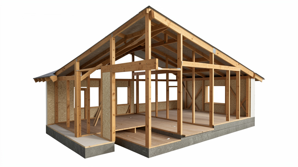
The Language of Structure: Key Terms for Confident Conversations
Fluency prevents misunderstandings with contractors and empowers informed decisions. These terms appear consistently in plans, permits, and professional discussions.
- Load-Bearing Wall: A wall supporting weight from above (roof, floors, other walls). Not all interior walls bear load. Exterior walls typically do. Clues: Runs perpendicular to floor joists above; has supporting structure directly below in basement/crawlspace; contains headers over openings; feels solid when tapped (though sound alone is unreliable). Verification is essential—never assume.
- Header: A horizontal beam spanning an opening (door, window) in a load-bearing wall. Transfers load to king studs and trimmer studs. Size depends on opening width and load above—never guessed.
- Joist: Horizontal members supporting floors or ceilings. Spaced consistently (12″, 16″, or 24″ on center). Floor joists support subfloor; ceiling joists support attic insulation/drywall (unless part of a truss system).
- Beam/Girder: A primary horizontal support carrying loads from multiple joists or walls. May be dimension lumber, LVL, or steel. Critical in open-concept modifications.
- Post/Column: Vertical support transferring load from beams to foundation. Must be plumb with adequate bearing area below and above.
- Truss vs. Rafter:
- Rafters: Individual sloped members forming roof frame, supported by ridge board and walls. Allow usable attic space.
- Trusses: Prefabricated triangular frameworks (chords and webs). Engineered for efficiency; webs create unusable attic space. Never cut, notch, or modify truss webs without explicit engineering approval—integrity of the entire roof system depends on the complete design.
- Footing/Foundation:
- Footing: Wide concrete base below frost depth, distributing house weight to soil. Wider than foundation wall.
- Foundation: Concrete or masonry wall transferring load from framing to footing. Types: basement, crawlspace, slab-on-grade.
- Deflection: Measurable bending of a structural member under load. Excessive deflection indicates serviceability issues (even without imminent failure).
- On Center (o.c.): Measurement between centers of adjacent framing members (e.g., “joists 16″ o.c.”).
- Bearing: The contact surface where a member rests on its support. Insufficient bearing risks crushing.
- Sheathing: Structural panels (plywood, OSB) applied to framing. Provides essential shear resistance (prevents racking) and distributes loads. Functions as structural skin, not just covering.
Identifying Load-Bearing Elements in Your Existing Home
Before any modification, systematic observation minimizes risk. When uncertainty exists, pause and seek professional verification.
Step-by-Step Identification Approach
- Begin in the Basement or Crawlspace (If Accessible): This reveals the structural skeleton.
- Locate the main beam (often steel or large LVL) running longitudinally. Posts support it.
- Walls directly above this beam are highly likely load-bearing.
- Walls running perpendicular to floor joists typically support them and are load-bearing. Walls parallel to joists are less likely (but verify—some support partitions above).
-
Note doubled joists or beams under concentrated loads (e.g., fireplace location above).
-
Examine the Attic (Safely and Cautiously):
- Stick-framed roofs (rafters): Walls directly under the ridge board or supporting purlins (mid-span braces) are typically load-bearing.
- Truss roofs: Load primarily transfers to exterior walls. Interior walls under trusses are often non-load-bearing for the roof—but may support floors above. Critical: Truss designs vary (e.g., scissor trusses transfer load differently). Look for manufacturer plates or consult original plans if available.
-
Distinguish collar ties (upper third of attic, resist wind uplift) from ceiling joists (which may carry attic load and tie walls together).
-
Analyze Interior Clues:
- Load-bearing walls often align vertically through floors. A first-floor wall directly under a second-floor wall warrants attention.
- Headers over doors/windows in an interior wall suggest load-bearing function. Carefully remove an outlet cover plate on the wall—use a flashlight to look upward inside the cavity for a solid header above the opening. (Restore cover plate immediately.)
-
Large open spans below (like a garage) often mean the wall above carries significant load.
-
Consult Available Documentation:
- Original structural drawings (if accessible) explicitly identify load-bearing elements and specifications. Your local building department may retain permit records with relevant drawings.
Signs Warranting Professional Assessment
- Cracking Patterns: Stair-step cracks in brick veneer; diagonal cracks radiating from window/door corners on a specific wall; cracks widening over time.
- Visible Deflection: Noticeable sag in roofline, floors, or ceilings. Verify with a level or taut string line.
- Operational Issues: Doors or windows sticking persistently in one area—may indicate framing movement.
- Evidence of Prior Modifications: Signs of previous wall removals, beam installations, or sistered joists. Unknown history increases uncertainty.
- Home Age and Framing Type: Pre-1950s homes may use balloon framing (continuous studs floor-to-roof), where many walls bear load. Older materials may have hidden deterioration.
Moving Beyond the “Knock Test”
Many suggest knocking on a wall: hollow sound = non-load-bearing; solid thud = load-bearing. This method is highly unreliable and should not be solely relied upon for structural decisions. Insulation density, stud spacing, drywall layers, and cavity contents heavily influence sound. A hollow-sounding wall could be load-bearing with wide stud spacing; a solid-sounding wall could be non-structural but densely insulated. Rely on structural clues (steps above) and documentation. When doubt remains, professional verification is the only responsible path.
Common Renovation Scenarios: Applying the Three Pillars
Real-world applications reveal where awareness prevents problems. These scenarios emphasize tracing load paths and respecting material limits.
Scenario 1: Removing a Wall for an Open Layout
- Load Path Question: What weight does this wall carry? Trace upward: Second-floor walls? Roof structure? Heavy fixtures?
- Critical Steps:
- Verify status using basement/attic clues and documentation. Never proceed on assumption.
- If load-bearing: A beam must carry the load previously supported by the wall. This beam spans between new supports (posts/columns), which must transfer load down to foundation or footing.
- Beam sizing is engineering-dependent: Span between supports, total load (dead + live), deflection limits, and material properties determine required size. Guessing risks sagging, finish damage, or structural compromise. Engineered drawings are essential.
- Temporary shoring: During removal, robust temporary supports (“strongbacks” with posts) must safely carry the load. Improper shoring causes immediate damage.
- Approach Options:
- Method A (Recommended): Engage a structural engineer for assessment, calculations, and stamped drawings ($800–$2,500). Hire a licensed contractor experienced in structural modifications ($5,000–$15,000+). Total investment reflects verified safety and code compliance.
- Method B (Not Recommended): Proceeding without engineering based on anecdotal advice (“a double 2×10 worked for my neighbor”). Risk includes inadequate support, permit denial, costly repairs later, and potential insurance complications for unpermitted work.
- Method C (Immediate Action): Stop work if structural uncertainty arises. Secure the area and consult a qualified professional before proceeding further.
Scenario 2: Adding a Deck Attached to the House
- Load Path Question: How do deck loads (dead, live, snow) transfer safely to stable ground without compromising the house structure?
- Critical Steps:
- Ledger Board Attachment: The ledger (board bolted to the house rim joist) is critical. Must be flashed meticulously to prevent water intrusion (a leading cause of connection failure). Bolts must be spaced per current code (typically 16″ o.c. with specific corrosion-resistant bolts). Never attach to brick veneer, siding, or roof overhangs—must bear directly on structural rim board.
- Footing Depth: Footings must extend below the local frost depth (varies by region: e.g., 42″ in northern climates, 12″ in mild zones). Shallow footings heave during freeze-thaw cycles, stressing connections.
- Beam and Joist Sizing: Calculate spans based on intended use. A hot tub or heavy furniture concentration requires higher live load capacity. Guardrails must resist specified lateral forces.
- Contextual Insight: Historical incidents, such as the 2015 Berkeley deck collapse, underscore that connection failures (due to improper fastening, hidden rot, or inadequate flashing) are often the root cause—not just member size. Your local building department’s deck construction guide is a vital, freely available resource. Adherence isn’t optional; it’s foundational to safety.
Scenario 3: Converting an Attic into Habitable Space
- Load Path Question: Attics were typically designed for light storage (10–20 psf live load), not living areas (40 psf live load + furniture). Can existing framing safely handle the increased demand?
- Critical Steps:
- Assess Roof Structure: Are rafters or trusses present? Trusses generally cannot be modified for headroom without engineered solutions (e.g., specialized “attic trusses” designed for habitation). Rafters may require reinforcement.
- Floor System Capacity: Existing ceiling joists are usually undersized for floor loads. A new floor system, supported by beams/posts bearing to foundation, is typically required.
- Stairwell Opening: Cutting joists for stairs requires headers around the entire opening to transfer severed joist loads.
- Egress and Openings: Bedroom code requires a rescue-sized window. Cutting a wall for this may affect structural integrity if load-bearing.
- Hidden Considerations: Added insulation, electrical, plumbing, and HVAC increase dead load. Ventilation requirements change. This project almost always requires structural engineering review. Initial cost estimates often rise upon professional assessment—but this reflects necessary safety measures, not inflated pricing.
Scenario 4: Installing Heavy Fixtures (Tile Floor, Stone Feature, Large Tub)
- Load Path Question: Concentrated dead loads demand localized verification and potential reinforcement.
- Critical Steps:
- Tile Floor: Ceramic or stone tile adds 3–5+ psf dead load. Over existing flooring? Total load may exceed joist capacity. Solution: Remove old flooring first; verify joist size/span; consider adding blocking between joists to minimize deflection (prevents tile cracking).
- Stone Fireplace/Mantel: A modest stone veneer section can weigh several hundred pounds. Must bear directly on a foundation wall or a beam supported continuously to footing. Never attach heavy stone directly to standard stud walls without verified reinforcement.
- Large Soaking Tub: A filled cast-iron tub can exceed 800 lbs. Concentrated on a small floor area. Verify joist size/span under the tub location; sistering joists or adding a supporting beam below may be necessary.
- Proactive Practice: When planning heavy installations, photograph the exposed framing before closing walls. Note joist size, spacing, span, and any existing blocking. This documentation aids future renovations and professional consultations.
When DIY Ends and Professional Help Begins: Clear Boundaries
Structural work involves skill, liability, and ethical responsibility. Knowing your limits reflects wisdom, not weakness. This section defines clear triggers for expert involvement.
Clear Triggers for Engaging a Structural Engineer
Consult a licensed structural engineer (P.E.) when:
– Removing, altering, or modifying any wall where load-bearing status is uncertain.
– Installing beams, headers, columns, or posts supporting floors, roofs, or other walls.
– Modifying roof trusses or major rafter systems.
– Adding significant dead load (heavy flooring, stone features, equipment) to existing framing.
– Addressing visible structural distress (significant cracks, sagging, bowing, persistent sticking doors/windows).
– Building decks attached to the house, especially elevated or complex designs.
– Working in regions with specific hazards: high seismic activity, high wind zones, expansive soils, or heavy snow loads.
– Your local building department requires engineered drawings for permit approval (common for structural modifications).
Why an Engineer, Not Just a Contractor? Contractors execute work; engineers design safe, code-compliant solutions. A reputable contractor will require engineered plans for structural work. Engineers analyze site-specific conditions (soil, climate loads, existing structure), calculate precise member sizes and connections, and provide stamped drawings that satisfy building officials. This process verifies safety—it’s not bureaucracy. The engineer’s stamp signifies professional responsibility for the design’s adequacy.
Questions to Ask Potential Contractors
When discussing structural work:
1. “Will this project require engineered drawings? Will you coordinate with an engineer, or should I engage one independently?”
2. “Can you share examples of similar structural projects, including permits and inspection records?”
3. “How will temporary shoring be designed and installed during critical phases like wall removal?”
4. “What is your protocol if unexpected conditions are found during demolition (e.g., rot, inadequate framing)?”
5. “Will all work comply with current IRC standards and local amendments? Will you secure all necessary permits?”
Red flags: “Permits aren’t needed for this,” “I’ve done this many times without plans,” reluctance to discuss engineering, shoring, or inspection processes.
Permits and Inspections: Your Safety Framework
Permits establish a verified safety pathway. The process:
1. Application: Submit plans (often requiring engineer stamp for structural work) to the building department.
2. Plan Review: Officials verify code compliance before work begins.
3. Inspections: Critical stages are verified during work:
– Footings/Foundation
– Framing (before enclosure)
– Final
Skipping permits bypasses these safeguards. Consequences include:
– Safety Risk: Undetected flaws remain hidden.
– Financial Risk: Unpermitted work may require exposure (removing finishes) for retroactive inspection, costly corrections, or complications during future home sales (buyer inspections flag unpermitted work; lenders may hesitate).
– Insurance Risk: Insurers may deny claims related to unpermitted structural modifications, citing failure to maintain the property per code standards.
View permit fees as investment in verified safety and future marketability.
Ethical Stewardship: The Ripple Effect
Your renovation choices extend beyond your household:
– Future Owners: Hidden structural compromises become someone else’s crisis years later.
– Community Safety: A failing deck or wall can endanger neighbors or passersby.
– Tradespeople Safety: Electricians, plumbers, and finishers working within a compromised structure face increased risk.
Choosing integrity—securing engineering when needed, obtaining permits, using appropriate materials—is a commitment to collective safety. Sharing your responsible process (“We had the beam design engineered”) normalizes best practices and elevates community standards.
Your Questions, Answered
Q: How can I tell if a wall is load-bearing without basement or attic access?
A: While full verification is ideal, look for interior clues: 1) Wall runs perpendicular to visible floor joists (e.g., in a garage ceiling below); 2) Doorways have substantial headers (visible as a thicker beam above the frame when checking carefully through an electrical outlet cavity with a flashlight); 3) Wall aligns vertically with a wall on the floor above; 4) It’s an exterior wall. However, absence of these clues doesn’t guarantee it’s non-load-bearing. When access is impossible, professional assessment is the only reliable path.
Q: Can I remove a small section of a load-bearing wall for a pass-through?
A: Yes, but only with proper engineering. The load must transfer around the opening via a correctly sized header beam. Header requirements depend entirely on opening width and the load above. A 3-foot pass-through needs a different header than a 6-foot opening. Never size a header based on prior installations or anecdotes—soil, roof design, and local climate loads vary. Engineered drawings ensure the header, supporting studs, and connections are appropriate for your specific conditions.
Q: My floor bounces when I walk. Is it unsafe?
A: Bounce (excessive deflection) is typically a serviceability issue rather than an immediate safety failure—but it warrants attention. Causes include: joists spanning near their limit; wider joist spacing; added dead load (heavy flooring); or degraded joists (moisture, insects). While sudden collapse is unlikely, chronic bouncing accelerates wear on finishes and framing. Solutions range from adding mid-span support beams below to installing blocking/bridging between joists. A structural professional can diagnose the cause and recommend targeted remediation.
Q: Are all drywall cracks a sign of structural trouble?
A: No. Hairline cracks at door/window corners often result from normal wood shrinkage or seasonal humidity shifts—common in newer homes. Cracks along drywall seams may indicate application issues. However, diagonal cracks radiating from openings, stair-step cracks in brick veneer, or cracks wider than 1/8 inch that grow over time can signal foundation movement or structural overload. Document cracks with dated photos. If they widen, multiply, or accompany sticking doors/windows, consult a structural engineer.
Q: Can I use steel beams instead of wood? Pros and cons?
A: Steel beams (I-beams, wide-flange) offer high strength-to-size ratios, enabling longer spans with less depth—useful for maximizing headroom. Pros: Non-combustible, resistant to insects/rot, consistent properties. Cons: Requires fireproofing (drywall enclosure) per code; conducts heat/cold (thermal bridging); needs corrosion protection; requires specialized cutting/fastening; connections must be precisely engineered; condensation risk in humid climates if not detailed correctly. Steel is excellent when designed by an engineer for your specific needs, but it’s not a simple material substitution. Total cost includes beam, engineering, installation expertise, and fireproofing.
Q: How do I know if my home’s original framing meets current code?
A: It likely doesn’t—and that’s generally acceptable. Building codes set minimum standards for new construction. Existing structures are typically “grandfathered” unless altered. The critical question isn’t “Does it meet today’s code?” but “Is it adequate for its current condition and intended use?” Original framing may have been sufficient for historical loads but inadequate for today’s heavier appliances, finishes, or changed room functions. When renovating, new work must meet current code, and alterations must not compromise existing structural safety. An engineer evaluates the entire system under proposed changes.
Q: What’s the most common structural oversight by homeowners?
A: Assuming silence equals safety. “The wall’s been there for decades, so removing a section can’t hurt.” Structure is dynamic. Materials degrade (moisture, insects). Loads change (renovations, storage habits). Environmental stresses accumulate. The absence of visible failure doesn’t prove adequacy—it may indicate failure is imminent. The second most common oversight is prioritizing aesthetics or budget over verified structural integrity. A beautiful space loses value if it’s unsafe. Respect the skeleton; the finishes will follow.
Q: Can I trust online span tables?
A: Exercise extreme caution. Span values depend on lumber species, verified grade stamp, moisture content, load duration, deflection limits, and local code amendments (snow, wind). An outdated table, one for commercial use, or one ignoring your region’s requirements is dangerously misleading. Reputable sources include: current American Wood Council Wood Structural Design Data publications, manufacturer tables for engineered wood (APA, LP, Boise Cascade), or resources from your state building code council. However, for any project affecting structural integrity, rely on calculations by a qualified professional using site-specific data—not generic tables.
Q: How does soil type affect my home’s structure?
A: Soil is the foundation’s foundation. Expansive clay soils swell when wet and shrink when dry, causing foundation movement (cracks, sticking doors). Sandy soils drain well but may shift. Poorly compacted fill settles unevenly. This is why footings must bear on undisturbed, stable soil at adequate depth. In challenging soil areas, foundations require specialized design (deeper footings, piers, soil stabilization). While homeowners rarely alter soil directly, understanding your soil type explains foundation behavior. Local building departments often have soil maps; geotechnical engineers assess specific sites for major projects.
Q: Is it ever acceptable to notch or drill joists/beams?
A: Yes, but within strict limits defined by code and engineering:
– Notching: Generally prohibited in the middle third of a span (high bending stress). Allowed near ends (within 1/4 span from support) but depth limited (e.g., ≤ 1/6 joist depth for sawn lumber). Never notch the tension edge (bottom of floor joists, top of ceiling joists where applicable).
– Drilling: Holes must be centered vertically in the web, away from edges. Diameter and spacing limits apply (e.g., max hole diameter = 1/3 joist depth; holes spaced ≥ 2x hole diameter apart). For engineered I-joists, never drill the flanges; web holes must follow manufacturer specifications exactly.
When uncertain—do not cut. Consult span tables, manufacturer guidelines, or an engineer. A misplaced notch or hole can significantly reduce capacity.
Q: What should I verify when hiring a structural engineer?
A: Confirm active licensure (check your state engineering board website). Seek experience with residential projects similar to yours (ask for examples). Verify professional liability insurance. Discuss their process: site visit? Detailed report with stamped drawings? Coordination with your contractor? Clarify fees upfront (often flat fee for defined scope). Trust your instincts—do they listen, explain concepts clearly, and prioritize safety? A strong engineer educates while solving the problem.
Q: After structural work, how can I verify it was done correctly?
A: Key indicators: 1) Work followed engineered drawings (request to review them); 2) All required permits were obtained and final inspection passed (secure certificate of completion); 3) Materials match specifications (e.g., LVL beam grade stamp visible); 4) Connections are correct (proper hangers, bolts, bearing); 5) No new cracks, sagging, or movement observed over time. Document thoroughly: photos during work, copies of permits, engineer’s report. A reputable contractor welcomes documentation and transparency.
Conclusion and Next Step
Understanding your home’s structure transforms uncertainty into informed stewardship. You now grasp the inseparable relationship of loads, spans, and strength—the physics governing every wall, floor, and beam. You can identify critical elements, recognize renovation pitfalls, and articulate precise questions to professionals. This knowledge isn’t about performing all work yourself; it’s about engaging wisely with experts, protecting your family’s safety, and preserving your home’s integrity for years to come.
Recap: The 3 Guiding Principles
1. Trace the Load Path: Before altering any element, ask: “What weight does this carry, and where does that weight travel next?” Never interrupt this path without a verified, engineered replacement route.
2. Respect the Span-Strength Relationship: Span isn’t arbitrary. Deflection increases exponentially with distance. Never estimate member sizes—rely on engineering verification or authoritative references specific to your project conditions.
3. Verify, Don’t Assume: “Looks solid” isn’t structural analysis. Use systematic identification methods. When uncertainty exists, professional assessment isn’t an expense—it’s the cost of certainty and safety.
The 24-Hour Rule: Before finalizing any renovation plan involving walls, floors, roofs, or foundations, pause. Within the next 24 hours:
1. Sketch a simple diagram of the area.
2. Draw arrows tracing where loads travel (apply the load path concept).
3. Write down one specific, informed question to ask a structural engineer or experienced contractor.
This small action embeds structural awareness into your decision-making, shifting you from reactive to proactive stewardship.
The Big Picture: Your home is a dynamic system, not just a collection of rooms. Its structure embodies generations of building science refined through innovation and hard-won lessons. By approaching it with curiosity, humility, and respect, you honor that legacy. You contribute to a culture where safety guides decisions, knowledge empowers action, and every thoughtful renovation strengthens—not weakens—the foundation of home.
Explore Our Complete Structural Literacy System:
Reading Your Home’s Blueprint: From Symbols to Structural Sense | Beam Sizing Demystified: Wood, Steel, and LVL Compared | Foundation Failures: Early Warning Signs Every Homeowner Must Know | The Renovation Permit Playbook: Navigating Approvals with Confidence | Deck Safety Deep Dive: Beyond the Ledger Board | When Cracks Speak: Decoding Foundation and Framing Distress Signals | Material Matters: Choosing Lumber, Fasteners, and Connectors for Longevity