From Soil Science to Structural Integrity: Your Step-by-Step Framework for Building Retaining Walls That Endure Generations
Retaining walls silently shape our landscapes—transforming precarious slopes into usable gardens, stabilizing foundations against erosion, and crafting terraced beauty from challenging terrain. Yet beneath their serene appearance lies profound engineering complexity. Without meticulous attention to soil dynamics, hydrostatic pressure, drainage pathways, and structural principles, even the most aesthetically pleasing wall becomes a liability waiting for heavy rain or seasonal shift. This definitive guide synthesizes geotechnical engineering standards, building code requirements, material science, and field-tested construction practices into an actionable framework. Whether you’re planning a modest garden terrace or addressing a significant slope stabilization challenge, these principles will empower informed decisions while emphasizing the non-negotiable truth: when structural integrity is uncertain, professional engineering consultation isn’t optional—it’s essential.
Introduction
Walk through any established neighborhood with rolling terrain, and you’ll encounter them: stone walls holding back lush lawns, timber borders defining garden beds, elegant concrete curves creating intimate patio spaces. Retaining walls represent humanity’s thoughtful dialogue with the land—shaping terrain not through domination, but through understanding natural forces. But this intersection demands respect. A failed retaining wall doesn’t merely disappoint aesthetically—it can trigger soil slides, damage foundations, destroy landscaping investments, and in severe cases, endanger property and people.
The difference between enduring success and catastrophic failure lies not in budget size or material prestige, but in understanding four foundational pillars that govern every retaining structure: comprehensive site assessment, scientifically appropriate design selection, uncompromising drainage management, and precision execution. These pillars transcend regional boundaries, material preferences, and project scales. They form a universal framework validated by decades of geotechnical research and documented failure analyses. This guide transforms these principles into actionable knowledge—demystifying soil classifications, decoding material specifications, illustrating drainage physics through tangible analogies, and providing construction sequences where each step builds logically upon the last. You’ll learn not just how to build, but why each detail matters, recognizing warning signs before they escalate and making confident choices aligned with your landscape’s unique demands. Always begin with this mindset: a retaining wall is first an engineered structure, second a landscape feature. Honor that sequence, and your wall will serve generations.
The Four Pillars Framework: Engineering Confidence Into Every Inch
Imagine constructing a bookshelf without knowing the weight of the books it will hold. Retaining walls face a similar peril when built without understanding the forces they must resist. Soil isn’t inert filler—it’s a dynamic, moisture-responsive material exerting continuous lateral pressure. The Four Pillars Framework eliminates guesswork by establishing a sequential decision pathway where each phase validates the next. This isn’t merely a construction checklist; it’s a cognitive model for thinking like an engineer while working like a craftsman. Master these pillars, and you’ll instinctively recognize when a project exceeds DIY scope—a critical safety insight no material catalog can provide.
Pillar 1: Site Assessment and Soil Analysis – Decoding What Lies Beneath
Before purchasing a single block or timber, invest time in understanding the ground itself. Soil composition dictates everything: required wall thickness, necessary reinforcement, drainage intensity, and even permissible wall height. Misjudging soil is consistently identified in geotechnical literature as a leading contributor to structural compromise—more than many construction errors combined. This isn’t academic nuance; it’s the bedrock of safety.
Why Soil Analysis is Non-Negotiable
Soil types behave dramatically differently under load and moisture:
– Clay soils expand significantly when wet, generating immense lateral pressure against walls. When dry, they shrink and crack, creating pathways for water infiltration.
– Sandy soils drain rapidly but lack cohesion; they behave like a fluid under saturation, increasing sliding risk at the wall base.
– Silty soils combine challenging traits: poor drainage like clay, low cohesion like sand. They’re highly erosion-prone.
– Loam (balanced mix of sand, silt, clay) offers ideal stability but is uncommon in undisturbed slopes.
– Organic soils (peat, muck) compress over time, causing uneven settlement. Never build directly on organic layers.
Geotechnical research consistently identifies soil misidentification as a leading factor in retaining wall failures, underscoring why preliminary analysis is non-negotiable. This foundational step prevents cascading errors later.
Conducting the Jar Test: Your Field Laboratory
You don’t need expensive equipment for preliminary analysis. The jar test provides reliable soil composition data:
1. Collect samples from 3–5 locations along your proposed wall line, digging 12–18 inches deep. Avoid surface debris.
2. Fill a clear quart jar one-third full with mixed soil samples. Add water to 1 inch below the rim. Add 1 teaspoon dish soap (breaks surface tension).
3. Seal tightly. Shake vigorously for 3 full minutes. Place on level surface.
4. Mark levels at precise intervals:
– After 1 minute: Sand settles (coarse particles). Measure height.
– After 2 hours: Silt layer forms. Measure cumulative height.
– After 24 hours: Clay settles. Measure total settled height.
– Floating layer: Organic matter (discard measurement).
5. Calculate percentages: (Layer height ÷ Total settled height) × 100.
Example Interpretation:
– 55% sand, 30% silt, 15% clay = Sandy Loam (generally stable; standard drainage sufficient)
– 20% sand, 30% silt, 50% clay = Clay Loam (requires enhanced drainage considerations, possible geogrid reinforcement)
– 10% sand, 15% silt, 75% clay = Heavy Clay (strongly recommend engineering consultation; high expansion risk)
Slope Geometry: Measuring True Challenge
Wall height alone is misleading. The critical metric is total retained height—vertical distance from the lowest point of retained soil to the top of the wall. Combine this with slope angle:
– Gentle slopes (5°–15°): Lower lateral pressure. Standard designs often suffice with proper drainage.
– Moderate slopes (15°–30°): Significant pressure increase. Requires careful batter (backward lean) and robust drainage.
– Steep slopes (30°+): High-risk scenario. Terracing (multiple shorter walls) is usually safer and more stable than one tall wall.
Practical Measurement Technique:
Use two 8-foot 2x4s and a level. Place one horizontally at slope base. Position second vertically against it at 90 degrees. Measure horizontal distance (run) and vertical rise over a consistent length (e.g., 4 feet). Slope percentage = (Rise ÷ Run) × 100. A 1-foot rise over 4-foot run = 25% slope (approximately 14 degrees). For accuracy beyond 30 degrees, use a smartphone inclinometer app calibrated against a known level surface.
Regional Environmental Factors
– Frost Depth: In freezing climates (USDA Zones 1–7, most of Canada, Northern Europe), footings must extend below the frost line to prevent heaving. Frost depths vary significantly by region. Consult your local building department—never guess.
– Seismic Activity: In earthquake zones (California, Pacific Northwest, Japan, New Zealand), walls require enhanced reinforcement: closer geogrid spacing, shear keys in concrete footings, or mechanical anchors. Building codes mandate specific seismic detailing.
– High Water Tables: Coastal areas, floodplains, or regions with heavy clay soils often have shallow water tables. Excavate a test hole 24 hours before building; if water accumulates, professional drainage design is essential.
– Expansive Soils: Common in Texas, Colorado, Arizona, and Australia. These clays swell dramatically when wet. Specialized designs with deep footings and robust drainage are non-negotiable. Local building departments often have specific requirements for these soils.
The Fundamental Principle: Soil is not a uniform medium—it is a living, breathing system with unique mechanical properties. Your wall design must converse with the soil, not fight against it. Test, observe, document, and design accordingly.
Pillar 2: Wall Type Selection Matrix – Aligning Material to Mission
Choosing a wall type based solely on aesthetics or initial cost invites future problems. Each material system has inherent engineering characteristics suited to specific conditions. This matrix eliminates emotional decisions by matching wall capabilities to your site’s documented requirements.
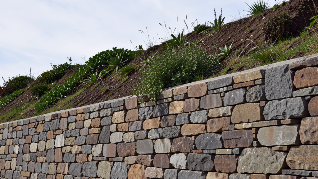
Segmental Retaining Wall (SRW) Systems: The Versatile Workhorse
Engineering Profile: Dry-stacked concrete units with interlocking pins/lips creating mass and friction. Geogrid reinforcement (polymer mesh) extends into retained soil, creating a unified “cohesive soil mass” for taller walls.
Ideal Applications:
– DIY projects up to 3–4 feet (unreinforced) on stable soil
– Engineered walls up to 40+ feet (with geogrid layers)
– Curved designs (many systems offer corner/wedge blocks)
– Areas requiring excellent drainage (open joints facilitate water escape)
Critical Construction Nuances:
– Base Preparation: 6–8 inches of compacted angular gravel (¾” minus). Plate compactor required—hand tamping is insufficient.
– Batter: Most systems require ½” to 1″ backward lean per foot of height. Verify with manufacturer specs.
– Geogrid Installation: For walls over 3 feet or challenging soils:
– Place geogrid on compacted backfill behind block course
– Extend grid 60–70% of wall height into retained soil
– Secure with pins; cover immediately with gravel to prevent displacement
– Space layers per engineering design (typically every 16″ of height)
Real-World Insight: Documented cases show properly installed SRWs with adequate drainage and reinforcement withstand significant weather events. One example: a 3.5-foot SRW on clay-loam soil in the Southeastern U.S. survived heavy seasonal rainfall due to geogrid every 16 inches, 12 inches of angular gravel backfill, and geotextile fabric.
Budget Adaptation: For walls under 2 feet on stable soil, omit geogrid but increase base width by 25% and ensure perfect compaction.
Critical Detail: Never use round pea gravel for backfill. Its smooth surface allows soil migration, clogging drainage paths within years. Always specify angular gravel.
Timber Walls: Rustic Charm with Lifecycle Awareness
Engineering Profile: Horizontal timbers anchored with rebar or deadmen (tiebacks extending into stable soil behind the wall). Relies on mass and anchoring rather than interlock.
Ideal Applications:
– Garden beds, low landscape borders (< 3 feet)
– Temporary erosion control (2–5 year lifespan)
– Budget-conscious projects where replacement is acceptable
Critical Material Specifications:
– Must be UC4B or UC4C rated for ground contact (pressure-treated with alkaline copper quaternary or micronized copper azole). Avoid “Above Ground Use Only” lumber.
– Minimum dimensions: 6×6 inches for walls over 2 feet; 4×4 acceptable only for very low borders (< 18″).
– Avoid creosote-treated railroad ties: Banned in residential use in EU/UK; leaches toxins into soil (harmful for vegetable gardens).
Anchoring Protocol:
– Drive ½” rebar vertically through timber joints every 4 feet
– For walls over 2.5 feet: Install deadmen every 6 feet—horizontal 2×8 timbers extending 4+ feet into slope, anchored with rebar
– Space courses tightly; gaps allow soil extrusion
Longevity Reality Check: Even properly treated timber lasts 10–15 years in moist climates. Document installation date; schedule replacement planning at year 8.
Modern Alternative: Composite timber-look blocks (recycled HDPE/plastic-wood fiber). Rot/insect-proof, but higher cost and requires specific anchoring techniques. Verify manufacturer compatibility with retaining applications.
Poured Concrete Walls: Maximum Strength for Demanding Sites
Engineering Profile: Monolithic reinforced concrete structure. Transfers lateral loads to deep footings. Highest structural capacity of common residential options.
Ideal Applications:
– Walls over 4 feet requiring permits/engineering
– Supporting driveways, structures, or heavy loads
– Curved or custom architectural shapes
– High-seismic or high-frost-depth regions
Non-Negotiable Construction Elements:
– Footing: Width = 2x wall thickness; depth below local frost line. Example: 8″ thick wall requires 16″ wide footing.
– Reinforcement: Minimum #4 rebar (½” diameter) spaced per engineering specifications. Seismic zones require closer spacing and larger rebar.
– Weep Holes: Install 1″ PVC pipes through forms before pouring at regular intervals, sloped slightly outward. Critical for pressure relief.
– Curing: Cover with plastic sheeting for 7 days; mist periodically. Prevents surface cracking from rapid moisture loss.
Common Pitfall: Skipping vibration during pour. Air pockets create weak points. Rent a concrete vibrator or repeatedly rod the mix with a ½” rebar piece.
Climate Adaptation: In freeze-thaw zones, specify air-entrained concrete (4–7% air content) to resist spalling. Ask your ready-mix supplier.
Mortared Stone or Brick Walls: Timeless Beauty Demanding Skill
Engineering Profile: Mass structure relying on mortar bond and skilled craftsmanship. Vulnerable to moisture damage if drainage is inadequate.
Ideal Applications:
– Decorative accents under 3 feet
– Historic property restoration
– High-end landscapes where craftsmanship is valued
Drainage Integration is Critical:
– Leave small gaps in mortar joints at base course every 3–4 feet for weep holes
– Fill gaps with pea gravel to prevent clogging
– Install perforated drain pipe behind wall base, wrapped in geotextile
– Backfill entire cavity with angular gravel (min. 12″ depth)
Dry-Stack Alternative: No mortar; relies on gravity and precise stone fitting. Only suitable for walls under 3 feet on stable soil. Requires significant masonry skill to achieve interlocking stability.
Preservation Insight: Historic stone walls often used “hearting”—smaller stones packed tightly behind face stones. Modern replicas should replicate this technique for stability.
Gabion Walls: Flexible Strength for Erosion Control
Engineering Profile: Galvanized or PVC-coated steel wire baskets filled with angular stone. Flexible structure absorbs ground movement; fully permeable.
Ideal Applications:
– Steep erosion-prone slopes
– Stream bank stabilization
– Modern industrial aesthetic landscapes
– Areas requiring vegetation integration
Installation Protocol:
– Stack baskets in stepped pattern (batter) for stability
– Fill with locally sourced angular stone (3″–6″ diameter)
– Use PVC-coated baskets in acidic soils or high-moisture areas for longevity
– For walls over 3 feet: Install geotextile fabric behind baskets before filling
Ecological Advantage: Native grasses and wildflowers readily seed through baskets, creating living walls that strengthen over time. Documented installations in agricultural regions show gabion walls planted with native groundcovers stabilizing slopes for over a decade while enhancing biodiversity.
Limitation: Industrial appearance not suitable for all landscapes; baskets may corrode over decades depending on coating quality and environment.
Wall Selection Decision Matrix
| Factor | Segmental Block | Timber | Poured Concrete | Mortared Stone | Gabion |
|---|---|---|---|---|---|
| Max DIY Height | 3–4 ft (unreinforced) | 3 ft | Not recommended | 3 ft (dry-stack) | 4 ft |
| Best Soil Match | All (adjust drainage) | Well-draining | All (with footing) | Stable, compacted | Erosion-prone |
| Drainage Priority | Critical (gravel backfill) | High | Critical (weep holes) | Critical (weep holes) | Self-draining |
| Lifespan | 50+ years | 10–20 years | 50+ years | 30+ years | 20–50 years |
| Skill Level | Moderate | Low | High | High | Moderate |
| Cost (Relative) | $$ | $ | $$$$ | $$$$ | $$$ |
| Permit Likelihood | Medium (over 3 ft) | Low (under 3 ft) | High (over 2 ft) | Medium | Low-Medium |
| Eco-Impact | Medium (concrete) | Medium (treated wood) | High (concrete) | Low (natural stone) | Low (stone) |
The Fundamental Principle: Material selection is an engineering decision first, aesthetic choice second. The right wall harmonizes structural necessity with site conditions—never forces a material into unsuitable conditions.
Pillar 3: Drainage and Hydrostatic Pressure Management – Defusing the Silent Threat
Water is the universal antagonist in retaining wall longevity. When soil saturates, hydrostatic pressure builds exponentially with depth—a physics principle that has compromised countless otherwise sound structures. Proper drainage isn’t an “add-on”; it’s the central nervous system of wall survival. This pillar transforms abstract pressure concepts into tangible, actionable systems.
Understanding Hydrostatic Pressure: The Physics Made Visible
Imagine pressing your palm against a swimming pool wall. At the surface, minimal pressure. At the deep end, significant force. Soil behind a wall behaves similarly when wet. The pressure increases with depth and soil saturation. For saturated soils at modest depths, pressure can exceed significant force per square foot—enough to move inadequately designed walls. Without drainage, this pressure seeks release by moving the wall, cracking mortar, or forcing soil through joints.
The Three-Layer Drainage System: Your Non-Negotiable Defense
Every wall over 18 inches requires this integrated approach:
- Perforated Drain Pipe (The Conduit):
- Use 4-inch perforated PVC pipe (holes pre-drilled) or corrugated pipe with fabric sock.
- Place directly behind wall base on 2–3 inches of gravel bedding.
- Slope continuously at minimum ¼” per foot toward daylight outlet (e.g., slope away from house foundation).
- Critical Detail: Wrap pipe in geotextile fabric before placing gravel. Prevents soil fines from clogging perforations.
-
Outlet Protection: Extend pipe 6+ inches beyond wall end; cover outlet with wire mesh to deter rodents.
-
Gravel Backfill Zone (The Filter & Flow Path):
- Backfill entire area behind wall (minimum 12 inches wide) with ¾” angular gravel (“¾ minus” includes fines for stability).
- Why Angular? Angular particles lock together, creating stable voids for water flow. Round pea gravel shifts and compacts, blocking pathways.
- Installation Sequence: After placing drain pipe, backfill gravel in 6-inch lifts. Lightly tamp each layer—over-compaction reduces permeability.
-
Geotextile Barrier: Place non-woven geotextile fabric (150 gsm minimum) between gravel zone and native soil. Prevents soil migration while allowing water passage. Overlap seams 6+ inches.
-
Weep Holes (The Pressure Release Valves):
- Segmental Walls: Leave open joints in base course; many blocks have built-in weep channels.
- Mortared Walls: Install 1″ PVC pipes through wall during construction at regular intervals, sloped slightly outward.
- Timber Walls: Drill ¾” holes through timbers at base course before stacking; align vertically.
- Maintenance Protocol: Inspect weep holes quarterly. Clear blockages with stiff wire. Spider webs and debris commonly obstruct flow.
Surface Water Diversion: The First Line of Defense
Drainage behind the wall is futile if surface water pours directly onto the retained soil. Implement these upstream controls:
– Roof Downspouts: Extend at least 10 feet away from wall area using rigid piping. Never discharge near wall base.
– Swales: Dig shallow, vegetated ditches uphill of wall to intercept runoff. Slope swale 2% toward daylight outlet.
– French Drains: For persistent surface water, install perforated pipe in gravel-filled trench uphill of wall, daylighting away from structure.
– Top-of-Wall Grading: Slope finished grade at top of wall 5% away from wall face (½” drop per foot). Prevents water pooling against wall.
Climate-Specific Drainage Adaptations
– Arid Regions (Southwest US, Australia): Infrequent but intense rainfall demands rapid drainage. Use larger gravel (1½”) in backfill zone; increase drain pipe slope. Consider secondary drain pipe at mid-height for walls over 3 feet.
– Humid/Tropical Climates: Constant moisture requires redundancy. Install two parallel drain pipes at base for walls over 4 feet. Use PVC-coated geogrid to resist degradation.
– Freeze-Thaw Zones: Ensure drain pipes extend below frost line or use heat tape on outlet sections in extreme climates. Ice blockage creates dangerous pressure buildup. Verify pipe slope prevents water pooling in low spots.
– High Rainfall Areas (Pacific Northwest, UK): Increase gravel backfill width to 18 inches. Specify higher-flow capacity pipe (6-inch) for walls over 5 feet.
Failure Case Study: The Cost of Omission
In a documented case from the Pacific Northwest, a mortared 3.5-foot stone wall failed after 18 months. Investigation revealed:
– Native clay backfill directly against wall
– No drain pipe or gravel zone
– Roof downspout discharged near wall
– Weep holes omitted during construction
During sustained rainfall, hydrostatic pressure exceeded wall capacity. The wall bulged outward significantly, cracking mortar and displacing stones. Repair costs substantially exceeded the original construction investment. The fix required complete dismantling, installing a proper drainage system, and rebuilding. This wasn’t a material failure; it was a drainage design failure. The lesson echoes across engineering literature: drainage investment prevents reconstruction costs.
The Fundamental Principle: Hydrostatic pressure is inevitable; wall failure is optional. A properly designed drainage system doesn’t just extend wall life—it makes structural survival possible.
Pillar 4: Construction Precision and Quality Control – The Ritual of Reliability
Perfect planning collapses without meticulous execution. Construction is where theoretical engineering meets physical reality. This pillar breaks the process into phased actions where precision at each step compounds into structural integrity. Rushing or skipping any phase creates latent weaknesses that manifest under stress.
Phase 1: Layout and Excavation – Defining the Battlefield
– String Line Precision: Use batter boards (2×4 frames) set 3–4 feet beyond wall line. Stretch mason’s line between boards. Verify right angles with 3-4-5 triangle method: measure 3 ft on one line, 4 ft on adjacent line; diagonal should be exactly 5 ft.
– Excavation Depth: Dig footing trench to required depth (below frost line if applicable). Width = 2x intended wall width. Example: 12-inch thick wall requires 24-inch wide trench.
– Trench Base Preparation: Slope trench base backward ¼” per foot (creates natural batter). Compact thoroughly with plate compactor. Verify level with long straightedge and bubble level.
– Critical Check: Before proceeding, place a test block/course in trench. Confirm it sits level and aligned. Adjust trench as needed—this is easier now than after base material is placed.
Phase 2: Base Preparation – The Unseen Foundation
– Material Specification: ¾” angular gravel (“road base” or “¾ minus”). Avoid crusher run with excessive fines—it compacts too densely, reducing drainage.
– Placement Protocol:
1. Pour 4 inches of gravel into trench
2. Compact with plate compactor (3 passes minimum)
3. Add remaining 2–4 inches to achieve total 6–8 inch depth
4. Compact again until surface shows no footprints
5. Re-check level and backward slope (batter)
– Why Compaction Matters: Uncompacted base settles unevenly under wall weight, causing cracks and misalignment. Plate compactors deliver significant force per square foot—hand tampers achieve far less. Renting is non-negotiable for walls over 2 feet.
– Exception Handling: If trench fills with water during rain, pump out completely and allow base to dry to “optimal moisture content” (forms ball when squeezed but crumbles when poked) before proceeding.
Phase 3: Wall Assembly – Course-by-Course Integrity
– First Course is Sacred: This course bears maximum load and sets alignment for entire wall.
– Set blocks/timbers meticulously level front-to-back and side-to-side
– Use rubber mallet (not metal hammer) to avoid chipping
– Verify alignment against string line every 4 feet
– Pro Tip: For segmental blocks, apply thin layer of coarse sand to base for micro-adjustments
– Batter Verification: Check backward lean after every course:
– Place level on wall face
– Insert spacer block of correct thickness under downhill end of level
– Example: For 1″ batter per foot on 2-foot course, spacer = 2″
– Adjust immediately if out of spec—errors compound with height
– Joint Staggering: Offset vertical joints by minimum ½ block length (like brickwork). Prevents continuous weak planes. Mark courses with chalk line if needed.
– Backfill Integration: After every 2–3 courses:
1. Place geotextile fabric against wall face
2. Install drain pipe on gravel bedding if at base level
3. Backfill gravel zone 6 inches deep
4. Lightly compact gravel
5. Continue wall construction
– Timber-Specific: Drill ¾” holes for rebar anchors before stacking. Drive 24″ rebar through joints every 4 feet. For deadmen on taller walls: attach horizontal 2×8 tiebacks with galvanized straps, extend 4+ feet into slope, anchor with rebar pins.
– Concrete-Specific: Vibrate concrete thoroughly after pouring each lift. Check form alignment hourly during pour. Install weep hole pipes before concrete sets.
Phase 4: Final Backfill, Capping, and Grading
– Top Layer Transition: Final 6 inches behind wall: backfill with native soil mixed with 30% compost. Supports vegetation without compromising drainage zone below.
– Top-of-Wall Grading: Create 5% slope away from wall (½” drop per foot) for 2–3 feet. Prevents water pooling against wall face.
– Capstones (Highly Recommended):
– For segmental walls: Use manufacturer-specific caps; pin or mortar in place
– For stone walls: Select flattest stones; set in mortar bed
– Function: Protects top course from weathering, provides finished appearance, prevents soil washout
– Vegetation Strategy: Plant shallow-rooted ground covers (sedum, thyme, ajuga) on retained slope. Avoid trees within 1.5x wall height distance (roots destabilize soil). Install drip irrigation away from wall face to minimize moisture behind structure.
Construction Quality Control Checklist
Print and use onsite:
– [ ] Footing trench width = 2x wall thickness
– [ ] Trench base compacted and sloped for batter
– [ ] Base gravel depth 6–8″, fully compacted, level verified
– [ ] First course perfectly level and aligned
– [ ] Batter verified after every course (1″ per foot standard)
– [ ] Vertical joints staggered minimum ½ block length
– [ ] Geotextile fabric installed before gravel backfill
– [ ] Drain pipe placed on gravel bed, sloped correctly, wrapped
– [ ] Gravel backfill zone minimum 12″ wide, compacted in lifts
– [ ] Weep holes clear and functional (test with water hose)
– [ ] Top grading slopes away from wall face
– [ ] Capstones installed securely
The Fundamental Principle: Construction excellence is built course by course, decision by decision. There are no insignificant details—only details whose significance becomes apparent too late.
Advanced Applications: Navigating Complex Terrain
Terracing Steep Slopes: Engineering Stability Through Staging
When natural slope exceeds 30 degrees, single-wall solutions become high-risk. Terracing—building multiple shorter walls stepped into the hillside—reduces effective height and pressure on each structure.
– Spacing Rule: Vertical distance between terrace walls should be at least 2x the height of the lower wall. Example: For a 3-foot lower wall, start next terrace 6+ feet above its base.
– Water Management: Each terrace must have independent drainage. Install swales between terraces to intercept runoff. Never allow water from upper terrace to discharge directly behind lower wall.
– Access Consideration: Design terrace widths to accommodate intended use (e.g., 8-foot width for garden beds, 12-foot for patios).
– Professional Boundary: Slopes over 45 degrees, total heights over 10 feet, or unstable soils (sliding history) require geotechnical engineering. Do not attempt DIY solutions in these scenarios.
Curved Walls: Blending Aesthetics with Structural Logic
Curves enhance visual appeal but introduce complex lateral forces.
– Minimum Radius Rule: For segmental blocks, minimum curve radius = 4x wall height. Example: 3-foot wall requires minimum 12-foot diameter circle. Tighter curves require specialized wedge blocks or cutting.
– Block Modification: Use masonry saw with diamond blade to create precise tapers. Wear full PPE (respirator, goggles). Cut blocks dry to avoid slurry.
– Reinforcement Adjustment: Curved sections experience higher outward pressure. Increase base width by 25% and add extra geogrid layers if engineered.
– Layout Technique: Drive stake at curve center point. Attach string equal to desired radius. Walk arc while marking ground with spray paint. Verify with multiple radius measurements before excavation.
Integrating Stairs and Access Points: Safety in Transition
Cutting stairs through a retaining wall requires structural integration:
1. Frame stair opening during initial layout with reinforced corners (double blocks, extra rebar in concrete).
2. Ensure stair structure has independent footings where possible. If attached to wall, engineer connection points to transfer loads properly.
3. Install non-slip treads (textured concrete, grooved timber, slip-resistant coating).
4. Add handrails meeting local code (typically 34″–38″ height, continuous grip).
5. Illuminate steps with low-voltage path lights or solar caps for nighttime safety.
Safety Imperative: Never compromise wall integrity for stair placement. If structural integration seems complex, design stairs adjacent to wall rather than through it.
Living Retaining Walls: Ecological Integration
For environmentally conscious projects:
– Modular Green Wall Systems: Plastic trays filled with soil and plants stack like blocks. Best for walls under 3 feet. Requires irrigation during establishment. Select native, shallow-rooted species.
– Hydroseeding Gabions: After filling baskets, spray seed mixture (grass, clover, wildflowers) onto soil-filled sections. Mist regularly until established.
– Bioengineering Techniques: In erosion-prone areas, combine structural walls with live stakes (willow, dogwood cuttings) planted in soil above wall. Roots bind soil over time.
Maintenance Note: Living walls require seasonal care—pruning, irrigation management, invasive species control. Factor this into long-term planning.
Navigating Regulations, Permits, and Professional Collaboration
When Engineering Consultation is Non-Negotiable
Retaining walls are among the most regulated landscape structures for valid safety reasons. Seek a licensed geotechnical or structural engineer if ANY apply:
– Wall height exceeds local permit thresholds (often 3–4 feet)
– Wall supports a driveway, structure, swimming pool, or heavy load
– Soil is unstable (expansive clay, loose sand, organic layers, evidence of prior slides)
– Property is in designated floodplain, seismic zone, or steep slope area (check local ordinances)
– Wall is within 10 feet of property line or adjacent structure
– Local building department requires stamped drawings for permit
Document Value: An engineer provides site-specific calculations for footing depth, reinforcement spacing, drainage capacity, and material specifications. This documentation often satisfies permit requirements and provides liability protection. Professional consultation cost is minor compared to failure consequences.
Demystifying the Permit Process
- Pre-Application Research: Contact local building department. Ask:
- “What is the maximum wall height without a permit?”
- “Do I need engineered drawings for walls over [X] feet?”
- “Are there special requirements for my zoning district?”
- Request written guidelines if available.
- Application Package: Typically requires:
- Site plan (property lines, existing structures, proposed wall location)
- Wall design details (height, length, materials, cross-section drawing)
- Engineer’s stamped drawings (if required)
- Application fee (varies widely)
- Inspection Schedule: Most jurisdictions require:
- Footing inspection (before base material placement)
- Reinforcement inspection (before backfilling for engineered walls)
- Final inspection
Schedule inspections 48+ hours in advance. Have permit visible onsite during work. - Neighbor Protocol: If wall is near property line:
- Review local “spite fence” or boundary wall ordinances
- Notify adjacent property owners in writing (creates goodwill, may be required)
- Obtain written agreement if wall serves as boundary structure
Hiring a Contractor: Vetting for Competence and Integrity
If DIY isn’t feasible, rigorous vetting prevents costly mistakes:
– License Verification: Confirm state/local license is active and covers retaining wall work. Check for disciplinary actions.
– Insurance Proof: Require certificate of insurance showing $1M+ liability coverage. Verify policy is current.
– Reference Validation: Ask for 3 references for similar retaining wall projects. Call them. Ask:
– “Were permits and inspections handled professionally?”
– “How were unexpected issues (soil problems, drainage) resolved?”
– “Was the site left clean and safe daily?”
– “Would you hire them again?”
– Contract Specifics: Ensure written contract includes:
– Detailed scope (materials, dimensions, drainage specs)
– Permit responsibility clearly stated
– Payment schedule tied to milestones (never >10% upfront)
– Warranty terms (materials and workmanship)
– Cleanup and debris removal provisions
– Red Flags:
– Pressure to start immediately without permits
– Cash-only payments or significantly underbid quotes
– Reluctance to provide references or license number
– Vague answers about drainage or soil preparation
Common Failure Patterns and Proactive Prevention
Documented failure modes reveal preventable patterns. Learn these to safeguard your investment:
Pattern 1: The Slow Bulge (Hydrostatic Pressure Buildup)
Symptoms: Wall curves outward mid-height; cracks radiate from center.
Root Cause: Inadequate drainage allowing water saturation behind wall.
Prevention: Install full three-layer drainage system without exception. Verify weep holes remain clear during annual inspections.
Repair Path: Requires partial or full dismantling. Install drain pipe and gravel zone. Never attempt to “push wall back” without addressing drainage—pressure will rebuild.
Pattern 2: The Uneven Settle (Base Failure)
Symptoms: Wall dips at one end; steps form between courses.
Root Cause: Inadequate base compaction or unstable soil under footing.
Prevention: Excavate to stable soil; compact base gravel thoroughly with plate compactor. Verify level before first course.
Repair Path: Jack up settled section (requires temporary bracing), excavate, rebuild base. Often necessitates professional assistance.
Pattern 3: The Leaning Tower (Insufficient Batter or Anchoring)
Symptoms: Entire wall tilts forward uniformly.
Root Cause: Built perfectly vertical without backward lean; or inadequate deadmen on timber walls.
Prevention: Incorporate 1″ batter per foot of height. Verify with level after every course. For timber walls over 2.5 feet, install deadmen per specifications.
Repair Path: Usually requires complete rebuild. Temporary bracing is dangerous and temporary.
Pattern 4: The Crumbling Cap (Weathering and Freeze-Thaw)
Symptoms: Top course spalling, cracking, or displacing.
Root Cause: Water penetration into top course; freeze-thaw cycles in cold climates.
Prevention: Install capstones. Slope top grading away from wall. Apply breathable masonry sealer to concrete/stone caps in freeze-thaw zones.
Repair Path: Replace damaged capstones; improve top drainage.
Long-Term Observation Protocol
Walls receiving annual proactive care last significantly longer than neglected structures. Implement this 15-minute seasonal ritual:
– Spring (Post-Thaw/Rain): Check for new cracks, bulges, leaning. Test weep hole flow with garden hose. Clear debris from drainage paths.
– Fall (Pre-Winter): Remove leaf litter from weep holes and top of wall. Trim vegetation growing against wall face. Verify surface grading sheds water away.
– After Major Events: Inspect following heavy rainfall (>2 inches in 24 hours), earthquakes, or significant freeze-thaw cycles.
Documentation Tip: Take annual photos from identical angles. Compare year-to-year to detect subtle movement early.
Maintenance and Longevity Enhancement
A retaining wall is a living component of your landscape—not “install and forget.” Proactive care transforms decades of service into generations of value.
Seasonal Maintenance Checklist
| Season | Critical Actions | Tools Needed |
|——–|——————|————–|
| Spring | Inspect for cracks/bulges; clear weep holes; check drainage flow; repair minor cracks; assess vegetation growth | Wire brush, hose, level, crack filler |
| Summer | Monitor vegetation near wall; ensure irrigation doesn’t saturate retained soil; check for insect activity (termites in timber) | Pruners, moisture meter |
| Fall | Clear debris from weep holes and top of wall; trim roots near wall; verify surface grading; prepare for winter | Rake, shovel, level |
| Winter | Avoid piling snow against wall; check after thaw cycles; never use salt-based deicers near wall base (damages concrete) | Snow shovel, sand for traction |
Repairing Minor Issues Before They Escalate
– Hairline Cracks (<1/8″): Clean with wire brush. Fill with hydraulic cement (expands as it cures) or epoxy injection kit. Smooth flush.
– Loose Blocks/Timbers: Disassemble affected section carefully. Inspect base and drainage. Replace damaged components. Rebuild with attention to alignment and compaction.
– Clogged Weep Holes: Insert stiff wire or small drain snake. Flush with hose. If persistent blockage, drill new weep hole adjacent to original.
– Vegetation in Joints: Remove carefully with hand tools. Avoid power washers—they force water behind wall. Apply targeted herbicide if needed (protect desirable plants).
When to Call a Professional Immediately
Do not attempt DIY repairs if you observe:
– Any measurable movement (leaning, shifting)
– Cracks wider than ¼ inch or growing longer
– Water consistently leaking through wall face (not weep holes)
– Bulging or bowing of wall face
– Damage to adjacent structures (patio cracks, foundation shifts)
Critical Safety Note: A failing retaining wall can collapse with little warning. If significant movement is observed, restrict access to area immediately and contact a structural engineer. Never stand directly in front of a compromised wall.
Landscaping for Longevity
– Plant Selection: Choose shallow-rooted ground covers (sedum, thyme, ajuga) for slopes above wall. Avoid trees within 1.5x wall height distance.
– Irrigation Management: Position sprinkler heads to avoid direct spray on wall face. Use drip irrigation placed away from wall base.
– Erosion Control: On steep slopes above wall, install erosion control matting before planting. Seed with fast-germinating grasses (ryegrass) for immediate soil stabilization.
– Wildlife Deterrence: Install wire mesh behind gravel zone in rodent-prone areas. Seal weep hole outlets with fine mesh to prevent nesting.
Your Questions, Answered
Q: What is the absolute maximum height for a DIY retaining wall?
A: There is no universal “safe” DIY height—it depends entirely on soil conditions, slope geometry, drainage, and local regulations. However, as a strong guideline: walls over 3 feet tall on anything but gentle slopes with ideal soil should involve professional engineering. Many jurisdictions require permits and engineered drawings for walls over 2–4 feet. Never let ambition override safety assessment. When in doubt, consult your local building department and a geotechnical engineer. The cost of consultation is trivial compared to failure consequences.
Q: Can I build a retaining wall right after heavy rainfall?
A: Absolutely not. Working on saturated soil compromises compaction and stability. Wait until soil reaches “optimal moisture content”—it should form a ball when squeezed in your hand but crumble easily when poked with a finger. Excavating wet soil creates unstable trench walls and prevents proper base compaction. If rain occurs during construction, cover excavated areas with tarps. Resume work only when soil conditions are appropriate. Patience here prevents costly settlement issues later.
Q: How do I calculate the exact number of blocks needed for my wall?
A: Follow this precise method:
1. Calculate total wall face area: Length (feet) × Height (feet)
2. Determine blocks per square foot: 144 ÷ (Block Length in inches × Block Height in inches)
Example: Standard block 16″ L × 8″ H → 144 ÷ (16 × 8) = 1.125 blocks per sq ft
3. Total blocks = Wall area × Blocks per sq ft
4. Add 5–10% for cuts, breakage, and future repairs
Pro Enhancement: Many manufacturers (Allan Block, Versa-Lok, Keystone) offer free online calculators. Input your dimensions, wall type, and local conditions for precise material estimates including base gravel, backfill, and geogrid requirements. Always round up—running short mid-project causes delays and mismatched batches.
Q: Is landscape fabric the same as geotextile fabric for drainage applications?
A: No—this is a critical distinction with performance consequences.
– Non-Woven Geotextile Fabric: Engineered for soil separation and filtration in civil applications. Made from needle-punched polypropylene fibers (100–150 gsm weight). Allows water passage while blocking soil fines. UV-stabilized for underground use. Required behind retaining walls.
– Woven Landscape Fabric: Designed for weed suppression in garden beds. Tighter weave that clogs easily under soil pressure. Degrades faster when buried. Unsuitable for drainage zones.
Always specify “non-woven geotextile fabric for drainage applications” when purchasing. Verify weight (gsm) meets manufacturer recommendations for your wall system. Never substitute cheap landscape fabric—it will fail prematurely.
Q: Can I attach a fence directly to my retaining wall?
A: Strongly discouraged. Fences add significant lateral and wind loads the wall wasn’t engineered to support. Fence post installation can compromise drainage systems and structural integrity. Instead:
– Install fence behind the wall (on upper level) with independent footings set below frost line
– Maintain minimum 12-inch clearance between fence posts and wall face
– If attachment is unavoidable (property line constraints), consult a structural engineer for reinforced connection details
This preserves wall integrity while meeting boundary requirements.
Q: How do I know if my soil is “expansive clay”?
A: Expansive clays swell dramatically when wet. Indicators:
– Soil forms hard, cracked clumps when dry; sticky, plastic-like mud when wet
– Jar test shows high clay content
– Local knowledge: Common in Texas, Colorado, Arizona, Oklahoma, parts of California
– Professional test: Atterberg Limits test (Plasticity Index >20 indicates high expansion potential)
If expansive clay is suspected, engineering consultation is essential. Solutions may include deeper footings, specialized drainage, soil replacement, or soil stabilization techniques. Never guess with expansive soils.
Q: What’s the difference between geogrid and geotextile fabric?
A: They serve distinct purposes:
– Geogrid: Polymer mesh (polyester/polypropylene) with open apertures. Function: Reinforces soil by interlocking with aggregate. Used horizontally between wall courses to create reinforced soil mass. Critical for walls over 3 feet.
– Geotextile Fabric: Non-woven felt-like material. Function: Separates gravel drainage zone from native soil while allowing water passage. Prevents clogging. Used vertically behind wall face.
Never substitute one for the other—they address different engineering needs. Follow wall system manufacturer specifications for type, placement, and overlap requirements.
Q: Do I need a permit for a 2-foot garden retaining wall?
A: Regulations vary significantly by municipality. While many jurisdictions exempt walls under 2–3 feet, exceptions exist:
– Walls supporting surcharge loads (soil piled higher behind wall)
– Walls within specific distances of property lines
– Walls in designated erosion control or steep slope zones
– Walls using certain materials (concrete may have different rules than timber)
Always contact your local building department before starting. Provide a simple sketch with dimensions. Get requirements in writing. The 15-minute phone call prevents costly stop-work orders or forced demolition later. When regulations are unclear, err on the side of permitting.
Q: Can plant roots damage my retaining wall over time?
A: Yes—strategically. Tree roots exert tremendous pressure:
– Keep trees at least 1.5x wall height away (e.g., 6 feet from a 4-foot wall)
– Avoid deep-rooted shrubs (bamboo, sumac) within 10 feet
– Select shallow-rooted ground covers for slopes above wall (sedum, thyme, creeping phlox)
– Install root barrier (HDPE plastic) vertically between wall and existing trees if relocation isn’t possible
Annual root inspection during maintenance checks prevents surprises. Early detection allows selective pruning before roots compromise structure.
Q: How long should I wait before backfilling a newly built wall?
A: Depends on wall type:
– Segmental Block (dry-stack): Backfill immediately after each 2–3 courses as described in construction sequence. No curing time needed.
– Mortared Stone/Brick: Wait minimum 48 hours after mortar sets before backfilling. Verify mortar is firm to touch. Backfill gently in thin lifts to avoid displacing stones.
– Poured Concrete: Wait minimum 7 days before backfilling. Concrete reaches significant strength at 7 days; full strength develops over weeks. Backfill carefully in 12-inch lifts with light compaction.
Rushing backfilling is a common cause of wall displacement. Follow material-specific timelines—patience ensures longevity.
Q: Is it safe to use old railroad ties for a vegetable garden retaining wall?
A: Strongly discouraged. Most old railroad ties are treated with creosote—a coal-tar derivative containing compounds known to leach into soil. Many countries restrict creosote-treated wood in residential settings. For edible gardens:
– Use untreated cedar or redwood (naturally rot-resistant)
– Choose composite lumber certified for ground contact
– Select concrete blocks or natural stone
– Verify material safety data sheets (MSDS) for any treated wood
Your family’s health is worth the modest material upgrade. When in doubt, choose non-toxic alternatives.
Conclusion and Your Path Forward
Retaining walls embody humanity’s thoughtful dialogue with the land—shaping terrain not through domination, but through understanding. They demand respect for natural forces while offering immense rewards: usable space where none existed, erosion control that protects ecosystems, and landscapes that inspire daily. This guide has equipped you with the Four Pillars Framework—not as rigid rules, but as a lens for seeing your project clearly. You now understand why soil testing precedes material selection, why drainage is non-negotiable physics rather than optional detail, and why construction precision compounds into generational durability.
The Three Immutable Principles
Carry these forward in every landscape decision:
1. Assess Before You Act: Never skip soil analysis, slope measurement, or regulatory verification. Knowledge eliminates fear and prevents catastrophic errors.
2. Drainage is Structural: Hydrostatic pressure isn’t a “maybe”—it’s a certainty after rain. Design drainage into every wall over 18 inches as rigorously as you design the wall itself.
3. Precision Compounds: The first course sets the trajectory for every course above. Compaction, batter, and alignment matter more than speed. Excellence is built incrementally.
The 24-Hour Rule: Your Commitment to Confidence
Before breaking ground, dedicate 24 hours to preparation:
– Hour 1–2: Contact local building department. Get permit requirements in writing.
– Hour 3–5: Perform jar soil tests at three points along proposed wall line. Document results.
– Hour 6–8: Sketch wall design with dimensions, noting drainage plan and material choices.
– Hour 9–12: Research contractors if DIY isn’t suitable. Verify licenses and request quotes.
– Hour 13–24: Reflect. Does this project align with your skills, time, and risk tolerance? When uncertainty exists, professional consultation isn’t failure—it’s wisdom.
The Legacy Perspective
A well-built retaining wall transcends function. It becomes part of your property’s story—a quiet testament to thoughtful stewardship. Future homeowners will walk past it without knowing the soil science, drainage physics, and construction precision embedded within. They’ll simply enjoy the leveled garden, the stabilized slope, the beauty born of respect for natural forces. That is the highest achievement of land shaping: creating structures so sound they become invisible in their reliability. Honor the craft. Respect the land. Build with intention. Your wall will stand not just for years, but for generations.
Explore Our Complete System:
Building a Paver Patio on a Slope: Grading and Drainage Mastery | DIY French Drain Installation: Step-by-Step Water Management | Soil Types Decoded: A Gardener’s Practical Handbook | Landscaping with Native Plants for Erosion Control | How to Read a Topographic Map for DIY Projects | Choosing the Right Contractor: A Step-by-Step Vetting Checklist | Terrace Gardening: Maximizing Small Sloped Spaces